Description
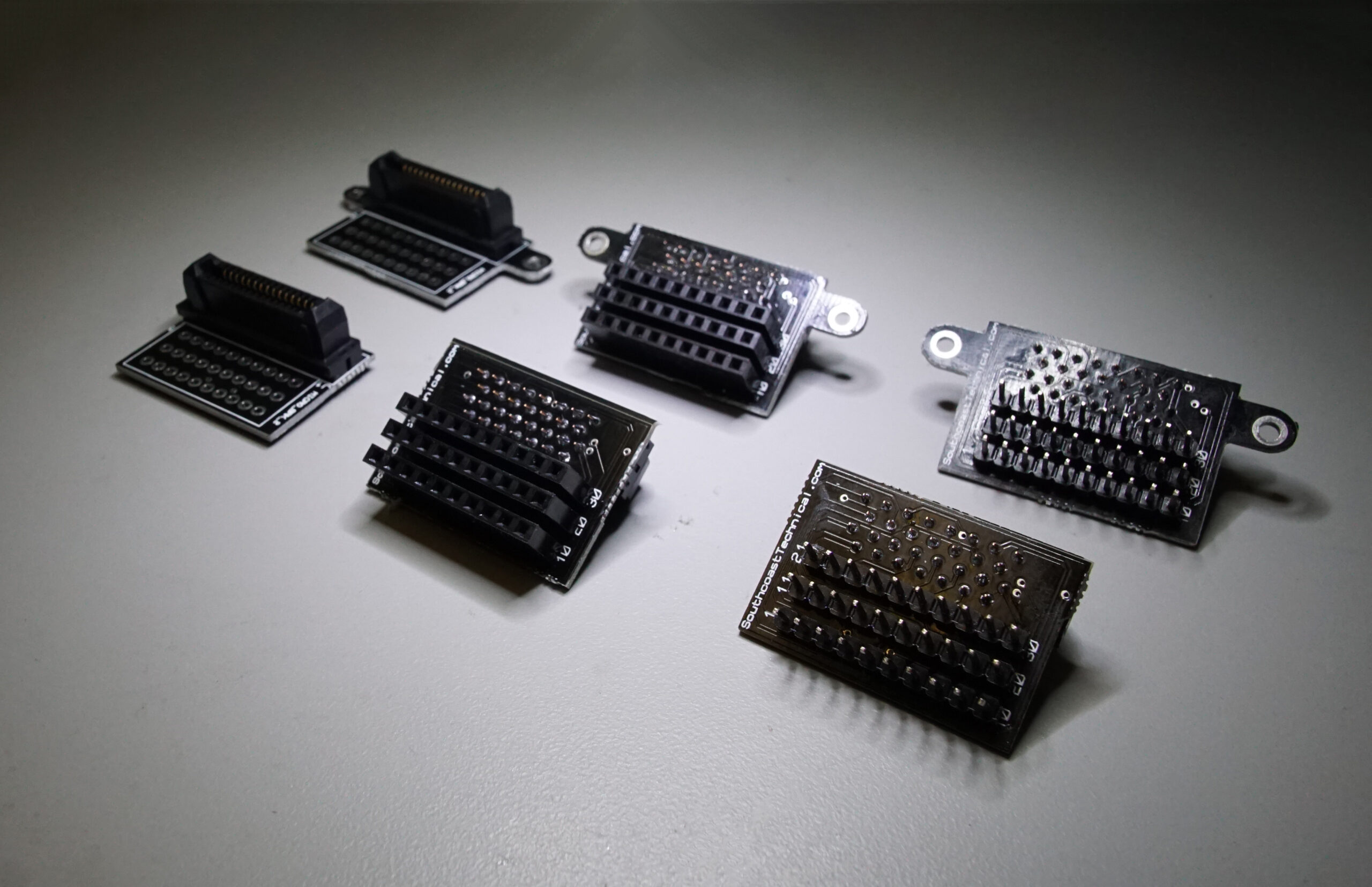
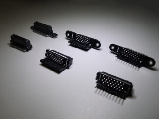
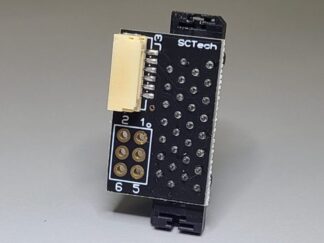
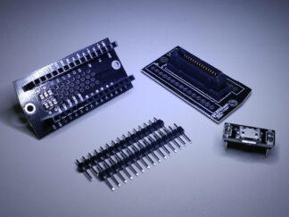
This board contains all connections from the Solo accessory bay port, broken out into three 10-pin 0.1″ pitch headers. The board is designed so it does not extend over the edge of the Solo bottom.
Available options:
- Your choice of headers: None, Kit, or Installed (note that when selecting ‘kit’ from the options bar, the picture does not show the headers. Rest assured they are included!)
- Header gender: Male/Female
- Mounting holes: Comes with screws to secure the breakout board to your Solo. These screws should be hand-tight only (5 ft-lbs max). It is recommended to apply a small amount of medium strength threadlocker, such as Loctite 242, to the screw prior to installation.
The pinout is identical to the 3DR documentation. It is replicated and expanded below for posterity.
| Internal Solo Accessory Board Pin# | External Breakout Board Pin# (THIS BOARD) | Name | Description |
| None | 1 | USB D- | Negative differential data signal to iMX6 OTG USB port. |
| None | 2 | USB D+ | Positive differential data signal to iMX6 OTG USB port. |
| 22 | 3 | FMU-SWDIO (Factory N/C) | To access this signal, you must connect a wire between pin 22 on the Solo mainboard and pin 22 on the accessory bay board, internally. |
| 21 | 4 | IO-SWDIO (Factory N/C) | To access this signal, you must connect a wire between pin 21 on the Solo mainboard and pin 21 on the accessory bay board, internally. |
| 19 | 5 | IO-PWM7 (Factory N/C) | To access this signal, you must connect a wire between pin 19 on the Solo mainboard and pin 19 on the accessory bay board, internally. |
| 18 | 6 | IO-PWM8 (Factory N/C) | To access this signal, you must connect a wire between pin 18 on the Solo mainboard and pin 18 on the accessory bay board, internally. |
| 16 | 7 | IO-USART1 TX (Factory N/C) | To access this signal, you must connect a wire between pin 16 on the Solo mainboard and pin 16 on the accessory bay board, internally. |
| 14 | 8 | IO-PWM6 (Factory N/C) | To access this signal, you must connect a wire between pin 14 on the Solo mainboard and pin 14 on the accessory bay board, internally. |
| 12 | 9 | SER5 TX (DEBUG) | UART5 TX output from Pixhawk™ 2. |
| 10 | 10 | SER2RT | UART2 RTS output from Pixhawk™ 2 for flow control. Connect to device’s CTS pin. |
| 8 | 11 | SER2Tx | UART3 RX signal to Pixhawk™ 2. Connect to device’s TX pin. Voltage is 3.3V. |
| 5 | 12 | CANH1 | CAN bus high to the Pixhawk™ 2. |
| 4 | 13 | CANL1 | CAN bus low to the Pixhawk™ 2. |
| 3,13 | 14 | GND | Ground reference on Solo system. |
| 1,2 | 15 | BATT | 12V to 16.8V. Maximum combined current off bus (pins 15 and 30) is 1.1A (fuse: 1812L110/24DR). Maximum combined power 18.5W. |
| 3,13 | 16 | USB GND | |
| None | 17 | +5V | 4.75V to 5.4V voltage pin for USB device. Maximum combined current off bus (pins 17 and 19) is 1.05A (fuse: ST890DTR). Maximum combined power 5.7W. |
| 23 | 18 | FMU-SWCLK (Factory N/C) | To access this signal, you must connect a wire between pin 23 on the Solo mainboard and pin 23 on the accessory bay board, internally. |
| None | 19 | +5V | 4.75V to 5.4V voltage pin for USB device. Maximum combined current off bus (pins 17 and 19) is 1.05A (fuse: ST890DTR). Maximum combined power 5.7W. |
| 20 | 20 | IO-SWCLK (Factory N/C) | To access this signal, you must connect a wire between pin 20 on the Solo mainboard and pin 20 on the accessory bay board, internally. |
| 3,13 | 21 | GND | Ground reference on Solo system. |
| 17 | 22 | IO-USART1 RX (Factory N/C) | To access this signal, you must connect a wire between pin 17 on the Solo mainboard and pin 17 on the accessory bay board, internally. |
| 15 | 23 | BUS ID | |
| 11 | 24 | SER5 RX (DEBUG) | UART5 RX input to Pixhawk™ 2. |
| 9 | 25 | SER2CT | UART2 CTS input to Pixhawk™ 2 for flow control. Connect to device’s RTS pin. |
| 7 | 26 | SER2Rx | UART3 TX signal from Pixhawk™ 2. Connect to device RX pin. Voltage is 3.3V. |
| 6 | 27 | 3DRID | USB ID pin for OTG port on iMX6 OTG port |
| 3,13 | 28 | GND | Ground reference on Solo system. |
| 3,13 | 29 | GND | Ground reference on Solo system. |
| 1,2 | 30 | BATT | 12V to 16.8V. Maximum combined current off bus (pins 15 and 30) is 1.1A (fuse: 1812L110/24DR). Maximum combined power 18.5W. |
3DR manufactured the Solo with internal mainboard pins 14-23 not connected to the accessory bay. Note that if you do not correctly wire the remaining internal mainboard pins to the accessory board inside your Solo, the pin names/descriptions above will be incorrect! If you’re a visual learner, see the picture in the following tutorial for the signal names on the internal pins. Click here for a tutorial for connecting the internal pins.
Reviews
There are no reviews yet.