Description
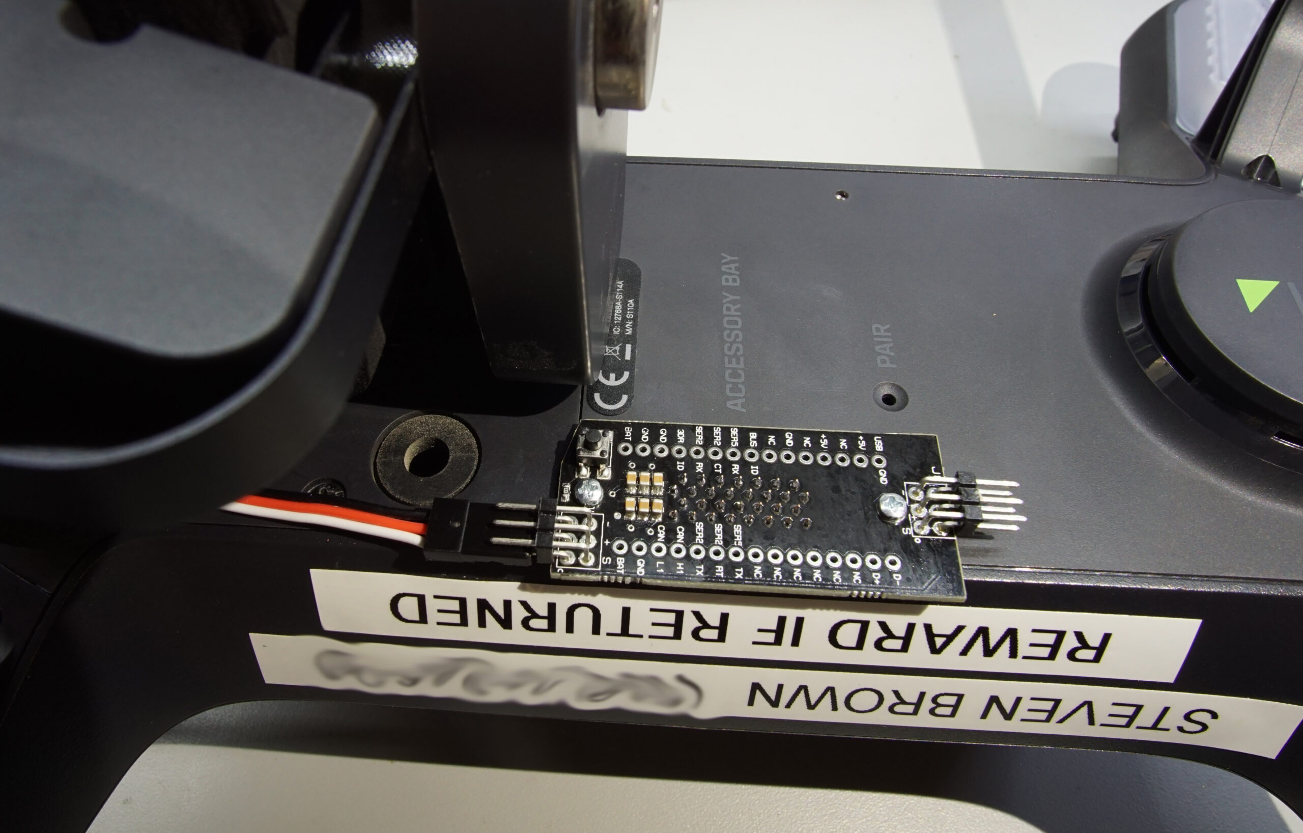
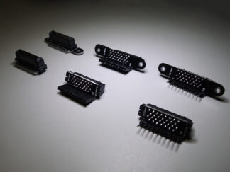
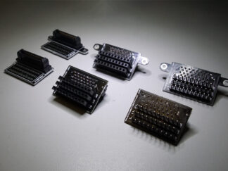
This breakout board connects to the 3DR Solo Accessory Bay connector and breaks out all connections (even the non-factory-connected ones).
SyncLight Connections
This board specifically has connections to power and synchronize four of our SyncLight anti-collision lights. The button on this board allows you to change the blink pattern of the SyncLights.
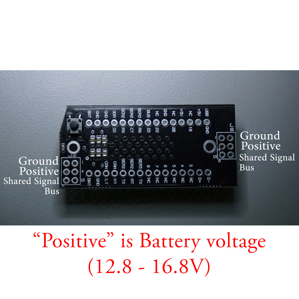
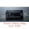
Please note that while the SyncLight connections physically fit a standard servo header, the voltage on the positive pin is the battery voltage of the Solo (12.8-16.8V). Attaching a regular servo to the SyncLight connections may fry your servo! SyncLights are designed for a wide voltage range (10-40V) and require a higher voltage than a normal servo.
If you don’t need the SyncLight connections, our standard breakout board might be of more interest to you.
The kit also includes mounting screws for securing the 3DR Solo Breakout Board to your 3DR Solo. This prevents the board from becoming separated from the 3DR Solo during flight. These screws should be hand-tight only (5 ft-lbs max). It is recommended to apply a small amount of medium strength threadlocker, such as Loctite 242, to the screw prior to installation.
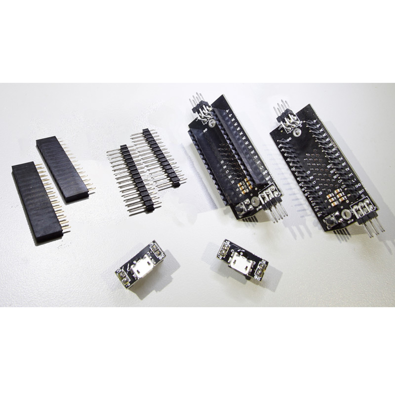
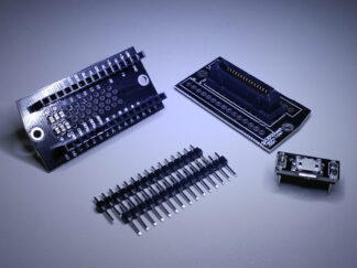
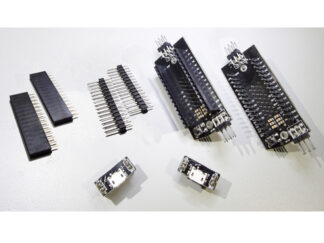
Available options include: headers (none, installed, or ‘kit’), header gender, and Micro-USB stack board (for easy USB access to the companion computer inside). The Micro-USB board is designed to be removable, with headers specific to the header gender you select for the main board (aka if you choose male headers for the breakout, the USB board will have female headers soldered on). The Micro-USB board is not intended to be permanently installed (soldered/glued), as it blocks access to the mounting screw underneath.
The board pinout follows the table found here. It is repeated and expanded below for posterity:
| Internal Solo Accessory Board Pin# | External Breakout Board Pin#(THIS BOARD) | Name | Description |
| None | 1 | USB D- | Negative differential data signal to iMX6 OTG USB port. |
| None | 2 | USB D+ | Positive differential data signal to iMX6 OTG USB port. |
| 22 | 3 | FMU-SWDIO (Factory N/C) | To access this signal, you must connect a wire between pin 22 on the Solo mainboard and pin 22 on the accessory bay board, internally. |
| 21 | 4 | IO-SWDIO (Factory N/C) | To access this signal, you must connect a wire between pin 21 on the Solo mainboard and pin 21 on the accessory bay board, internally. |
| 19 | 5 | IO-PWM7 (Factory N/C) | To access this signal, you must connect a wire between pin 19 on the Solo mainboard and pin 19 on the accessory bay board, internally. |
| 18 | 6 | IO-PWM8 (Factory N/C) | To access this signal, you must connect a wire between pin 18 on the Solo mainboard and pin 18 on the accessory bay board, internally. |
| 16 | 7 | IO-USART1 TX (Factory N/C) | To access this signal, you must connect a wire between pin 16 on the Solo mainboard and pin 16 on the accessory bay board, internally. |
| 14 | 8 | IO-PWM6 (Factory N/C) | To access this signal, you must connect a wire between pin 14 on the Solo mainboard and pin 14 on the accessory bay board, internally. |
| 12 | 9 | SER5 TX (DEBUG) | UART5 TX output from Pixhawk™ 2. |
| 10 | 10 | SER2RT | UART2 RTS output from Pixhawk™ 2 for flow control. Connect to device’s CTS pin. |
| 8 | 11 | SER2Tx | UART3 RX signal to Pixhawk™ 2. Connect to device’s TX pin. Voltage is 3.3V. |
| 5 | 12 | CANH1 | CAN bus high to the Pixhawk™ 2. |
| 4 | 13 | CANL1 | CAN bus low to the Pixhawk™ 2. |
| 3,13 | 14 | GND | Ground reference on Solo system. |
| 1,2 | 15 | BATT | 12V to 16.8V. Maximum combined current off bus (pins 15 and 30) is 1.1A (fuse: 1812L110/24DR). Maximum combined power 18.5W. |
| 3,13 | 16 | USB GND | |
| None | 17 | +5V | 4.75V to 5.4V voltage pin for USB device. Maximum combined current off bus (pins 17 and 19) is 1.05A (fuse: ST890DTR). Maximum combined power 5.7W. |
| 23 | 18 | FMU-SWCLK (Factory N/C) | To access this signal, you must connect a wire between pin 23 on the Solo mainboard and pin 23 on the accessory bay board, internally. |
| None | 19 | +5V | 4.75V to 5.4V voltage pin for USB device. Maximum combined current off bus (pins 17 and 19) is 1.05A (fuse: ST890DTR). Maximum combined power 5.7W. |
| 20 | 20 | IO-SWCLK (Factory N/C) | To access this signal, you must connect a wire between pin 20 on the Solo mainboard and pin 20 on the accessory bay board, internally. |
| 3,13 | 21 | GND | Ground reference on Solo system. |
| 17 | 22 | IO-USART1 RX (Factory N/C) | To access this signal, you must connect a wire between pin 17 on the Solo mainboard and pin 17 on the accessory bay board, internally. |
| 15 | 23 | BUS ID | |
| 11 | 24 | SER5 RX (DEBUG) | UART5 RX input to Pixhawk™ 2. |
| 9 | 25 | SER2CT | UART2 CTS input to Pixhawk™ 2 for flow control. Connect to device’s RTS pin. |
| 7 | 26 | SER2Rx | UART3 TX signal from Pixhawk™ 2. Connect to device RX pin. Voltage is 3.3V. |
| 6 | 27 | 3DRID | USB ID pin for OTG port on iMX6 OTG port |
| 3,13 | 28 | GND | Ground reference on Solo system. |
| 3,13 | 29 | GND | Ground reference on Solo system. |
| 1,2 | 30 | BATT | 12V to 16.8V. Maximum combined current off bus (pins 15 and 30) is 1.1A (fuse: 1812L110/24DR). Maximum combined power 18.5W. |
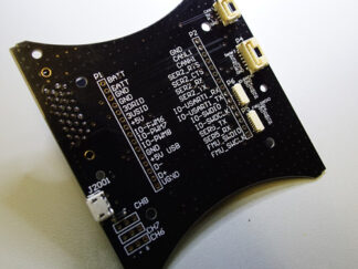
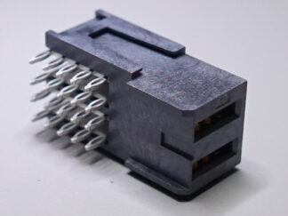
If you’re looking at the breakout board and you can see the capacitors, pin 1 is top right, and the numbers increase clockwise.
3DR manufactured the Solo with internal mainboard pins 14-23 not connected to the accessory bay. Note that if you do not correctly wire the remaining internal mainboard pins to the accessory board inside your Solo, the pin names/descriptions above will be incorrect! If you’re a visual learner, see the picture here for the signal names on the internal pins.
Reviews
There are no reviews yet.