


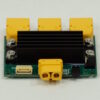
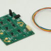

Description
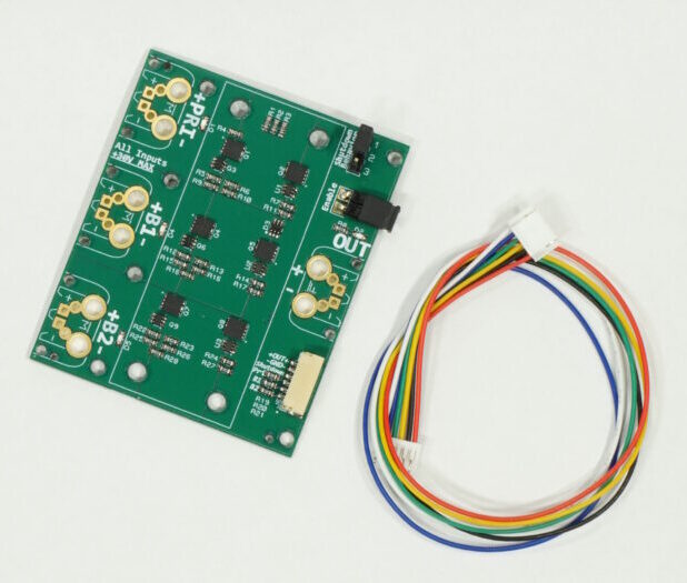
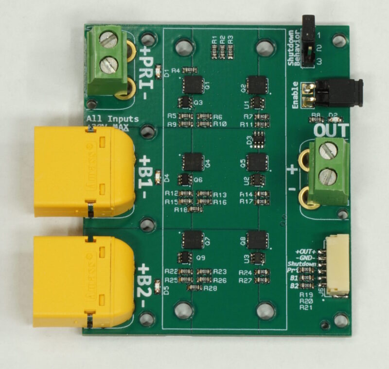
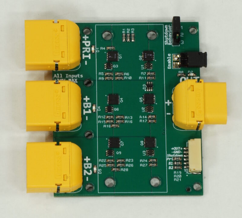
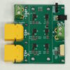
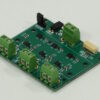
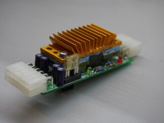
This board integrates three channels of an Ideal Diode circuit & associated P-channel MOSFETs to allow disparate voltage supplies or batteries to power a single output rail. The input priority feature allows a lower-voltage mains supply (like a 12V power brick) to be the sole provider of power even when a higher voltage source (like a 3S, 4S, etc battery) is applied to the “backup” inputs. When the priority power supply is removed, the backup batteries take over. Each channel can handle at least 15-20A, read on for more details.
Product Features:
- Seamless Backup Power: Two “Backup” channels provide power to the output rail when the “Priority” input is unavailable, with selectable behavior. See details below.
- Enable Functionality: An “Enable” jumper allows you to disable all inputs completely, minimizing leakage power consumption to <5µA. One switch controls all three channels while maintaining isolation!
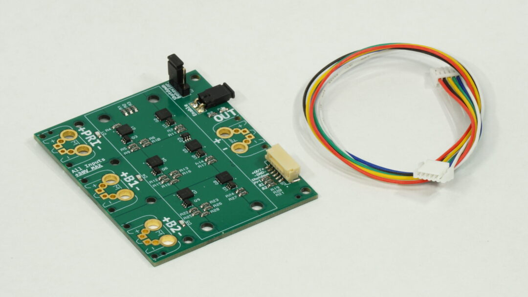
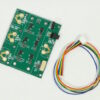
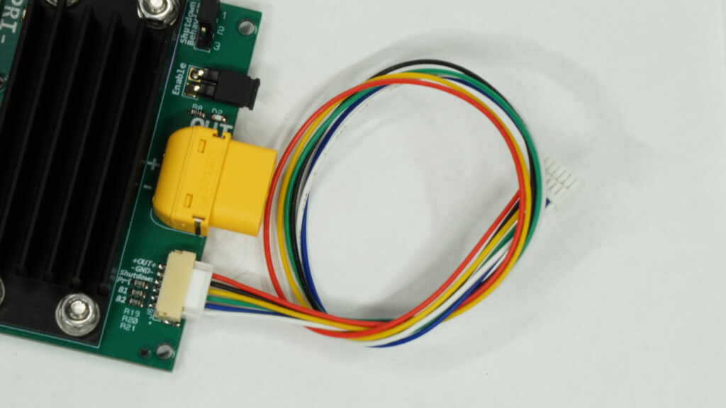
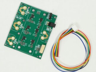
- Microcontroller Integration: A 6-pin monitoring connector allows for easy integration with a microcontroller. It provides:
- Output rail power (up to 1A) for downstream devices.
- Logic-level shutdown control for precise input management.
- Voltage monitoring of each input behind a 100kΩ resistor for isolation and safety.
- Reverse Polarity*/Reverse Current Protection: Prevents accidental reverse polarity* input reaching the output, and prevents backfeeding between inputs.
- Input Voltage Requirements: Each input channel operates independently and requires a minimum of 5V to fully activate, and is rated for input voltages up to +30V per channel.
- The module may activate as low as 3V, but will have a much reduced capability due to the weaker MOSFET gate drive voltage.
- Input Status LEDs: Visual feedback for active and selected inputs in the ideal diode circuitry.
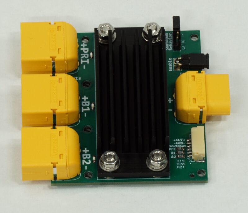
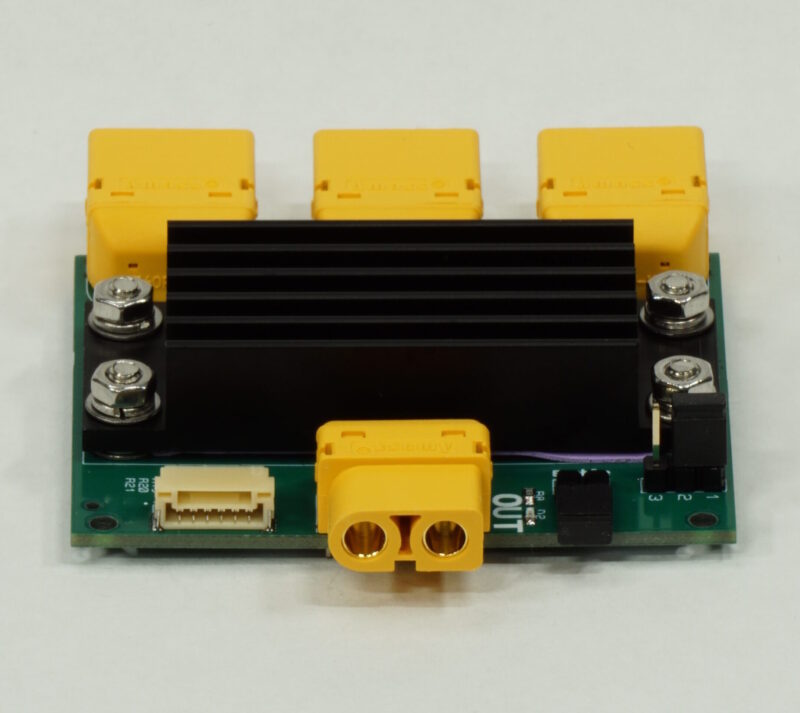
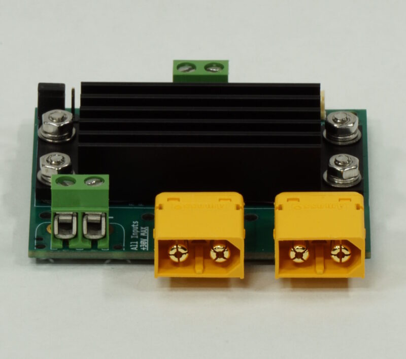
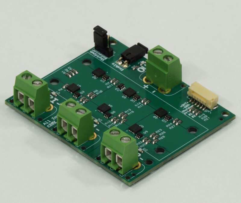
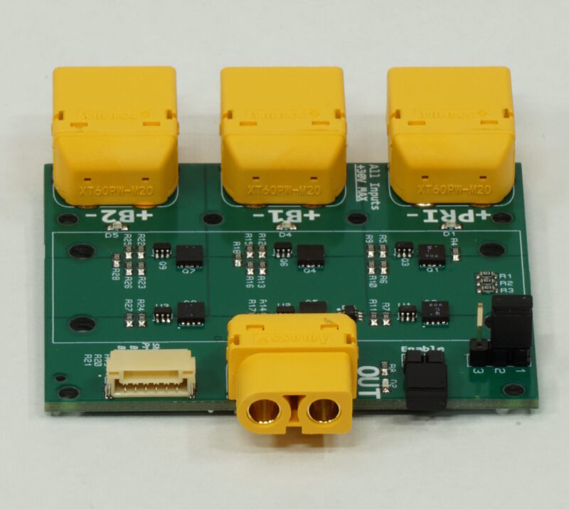
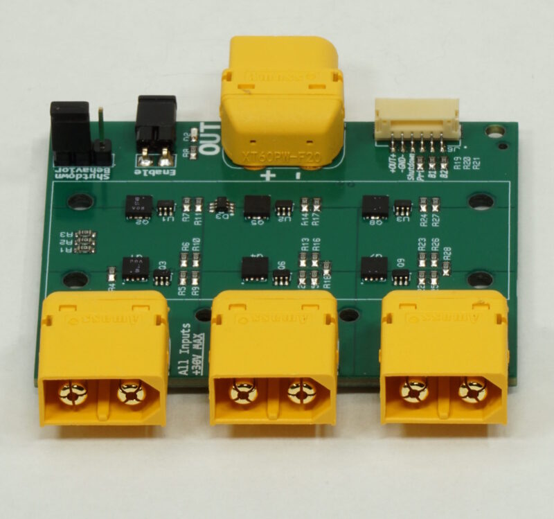
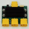
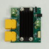
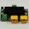
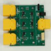
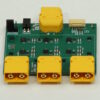
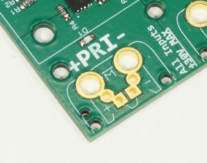
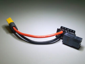
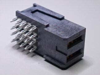
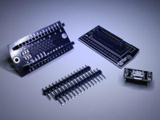
- Flexible Connection Options: Each input features a 3-in-1 footprint, allowing for versatile connections based on your needs
- See Specs & Ordering Info tab for more info
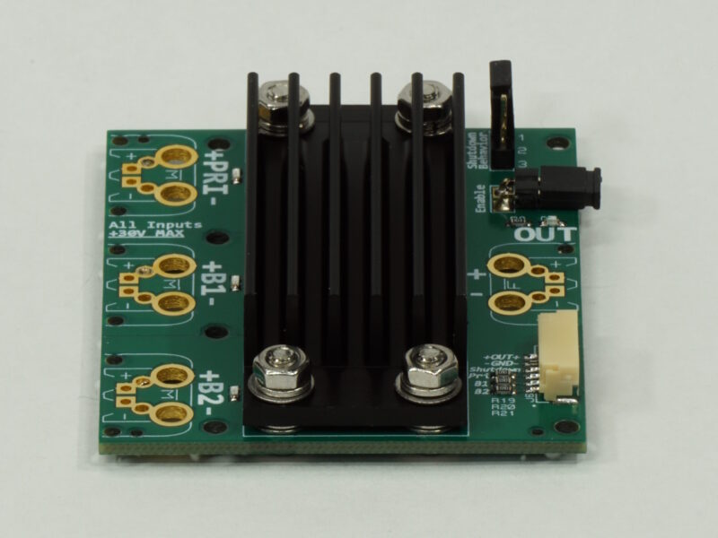
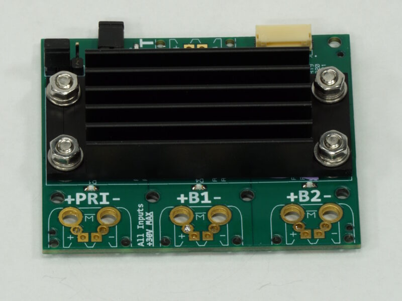
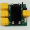
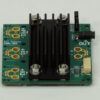
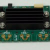
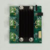
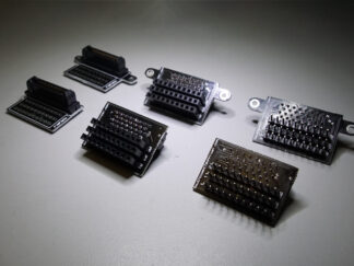
- Optional Heatsink for reduced temperatures/increased capacity
Board Ratings:
Reverse Polarity
This board will prevent your downstream circuitry from getting negative voltage if you accidentally wire input power backwards! The inputs have a maximum reverse voltage of -30V, but that may be de-rated based on other inputs:
Reverse voltage protection will vary depending on any voltage present at the Output, with a maximum reverse rating of -30V. For example, if one input is providing +12V to the Output (or there’s a 12V battery attached to the Output connector), the minimum reverse voltage protection rating will be reduced to -18V, due to the Positive + Negative voltage adding up to the rated 30V differential limit.
* Reverse polarity protection is only effective for power sources that do not share a common ground. This module has a shared ground plane across all input and output connectors. If a non-isolated, mains-referenced power supply is connected in reverse to an input while another non-isolated, mains-referenced power supply (with a shared ground) is correctly connected to a different input, a direct current path will form from the reversed source through the module’s ground plane to the correctly connected supply’s ground, bypassing the module’s protection circuitry.
Current Rating
⚠ Caution: The board can reach temperatures that may cause burns. Use care when handling. ⚠
Each channel can independently handle 15A-20A continuously. The upper bound depends on environmental conditions, desired max board temperature, and airflow.
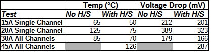
- In a room-temperature environment with no airflow and no heatsink, a continuous 15A draw will bring the hottest part of the board to ~65°C after one hour, while a continuous 20A draw will cause the board to quickly exceed 100°C, reaching a maximum of 125°C after one hour. The board will still operate at this load/temperature, but you may reduce the product lifespan with such extreme temperatures.
- Adding a heatsink increases the safe current rating from 15A/channel to 20A/channel – a continuous 20A draw only causes the board to reach 75°C after an hour.
- See below table for more detail.
Simultaneous Max Load:
- The board cannot sustain all three channels at maximum current simultaneously.
- If current is split equally across all three inputs, the board can handle:
- 10A per channel continuously (30A total) without a heatsink.
- 15A per channel for about 10 minutes
- 15A per channel continuously (45A total) with a heatsink.
- 20-25A per channel for about 1 minute
- 10A per channel continuously (30A total) without a heatsink.
Note: Current ratings assume an input voltage of 12V or greater. Lower voltages may slightly reduce total current capacity due to decreased MOSFET gate drive strength.
Each channel has approximately 0.014Ohms (14mOhm) of resistance at an input voltage of 12V. Resistance increases with temperature, leading to a higher voltage drop at sustained high currents. See below table for more detail.
“Enable” vs. “Shutdown”
Note: The “Enable” jumper and “Shutdown” pin serve distinct purposes in input power management and are not interchangeable.
- Enable Jumper:
- Acts as a master switch for the board, disconnecting all inputs from the circuitry when open.
- Designed for permanent installations where an external switch can toggle the entire system on or off.
- Extremely low off-current (<5µA) when disabled.
- Floating contact—it must be shorted rather than driven by a logic-level signal. Any current flowing through the Enable pin will turn the board on.
- If microcontroller control is needed, use a relay rather than a direct GPIO connection.
- Shutdown Pin:
- Provides fine-grained control for microcontroller integration when the board is enabled.
- A logic-level “high” (>2V) signal shuts down channels as configured by the “Shutdown Behavior” jumper, see details below.
- Please be aware, this feature does not completely disconnect inputs—each input channel will still present an approximate 5kΩ load to the source when shut down.
Selectable Priority/Shutdown Behavior
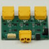
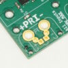
Near the OUT connector is a 3-pin header which is used to control the behavior of the board – both in normal operation and when it gets a “Shutdown” signal from a connected microcontroller.
- With the jumper across the 1&2 position, the board is in “Normal Priority Operation“: Backup Inputs activate only when the Priority Input is unavailable or a Shutdown signal deactivates it. A Shutdown signal only disables the Priority Input.
(Good for having wall power plugged into Priority Input, and hot-swappable batteries in the Backup Inputs. Wall power is always used, when available!) - With the jumper removed, the board is in “All-Channel Operation (Priority Shutdown Only)“: Backup Inputs are active regardless of Priority Input status (standard Ideal Diode behavior). A Shutdown signal only disables the Priority Input.
(Good for failing over to Backup power before unplugging Priority power under load – to prevent sparking on disconnect) - With the jumper across the 2&3 position, the board is in “All-Channel Operation (All Inputs Shutdown)“: Backup Inputs are active even if Priority Input is present (standard Ideal Diode behavior), but a Shutdown signal disables all inputs, de-energizing the output rail.
(Good for microcontroller-driven power-down modes!)
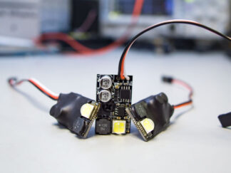
Here’s a visual, with all inputs powered, showing what happens when the board gets a shutdown signal in each of the three modes:
Why Should I Buy This Board Instead of Cheaper Ideal Diode Modules?
If you’ve browsed eBay, AliExpress, or Amazon, you’ve probably seen ideal diode modules for a fraction of this price. So, what makes this one worth it?
Most cheap ideal diode modules:
- Cannot fully turn off – The MOSFET’s body diode still conducts, keeping power flowing even if the controller can be “disabled.”
- Require multiple external switches or relays – If you wanted to maintain isolation, you’d need a separate switch for each input.
- Lack priority logic – If you want one input (like AC wall power) to always take precedence over a battery, you’d have to add your own circuitry.
The BrownieBoards Solution:
We designed this board because we needed something that:
✔ Provides true zero-power shutdown – One switch cuts off all three inputs without any residual power drain. When off, the board draws no more power than a battery self-discharging.
✔ Simplifies power management – A single enable switch controls all inputs while maintaining isolation.
✔ Includes built-in priority logic – “Shore power”/”wall power” always takes over when present, configurable via jumper.
By the time you add all the missing features to a cheap module, you’ve spent more money and time than if you’d just bought a well-designed board in the first place.
If you need reliable power switching, seamless priority handling, and input isolation—all without extra wiring or external components—this board is built to make your life easier.

Reviews
There are no reviews yet.